

David J.古肯贝格尔一,西奥多斯E德格鲁特一,Alwin M.D.万2,David J.Beebe一Edmond W.K.Young2,*
一生物医学工程系,Wisconsin Institutes for Medical Research,University of Wisconsin-Madison,麦迪逊,WI美国
2机械工业工程系,University of Toronto,国王学院路5号,MC313,Toronto,在,加拿大。
*通讯作者,E-mail: eyoung@mie.toronto.ca;电话:+1(416)978 1521
为什么这个有用?
…………………………Micromilling is a highly efficient method for fabricating microfluidic devices directly in polymeric materials like thermoplastics.请参阅Guckenberger及其同事的评论文章,了解微加工的入门知识。一将工件固定在铣床工作台上后,2铣削过程的下一步是align the tool对于工件,从而定义坐标原点。Many high-end mills designed for micromilling have automated tool alignment systems.然而,也能研磨微装置的低成本研磨机可能没有刀具对准系统,因此,用户必须手动将工具对准工件,以达到所需的精度。Here we present several alignment techniques that are low cost and can be performed by minimally trained users.We divide tool alignment into two separate directions: the verticalz-轴方向,and the planarX-Yplane direction.
What do I need?
- 数控铣床(PCNC 770,Tormach)
- 工具,e.g.选择的端铣刀
- Workpiece (properly secured to milling table,see ref.〔2〕
每种技术所需的特定工具或材料在下文单独引用。under the "Tooling Note".
What do I do?
Z轴方向
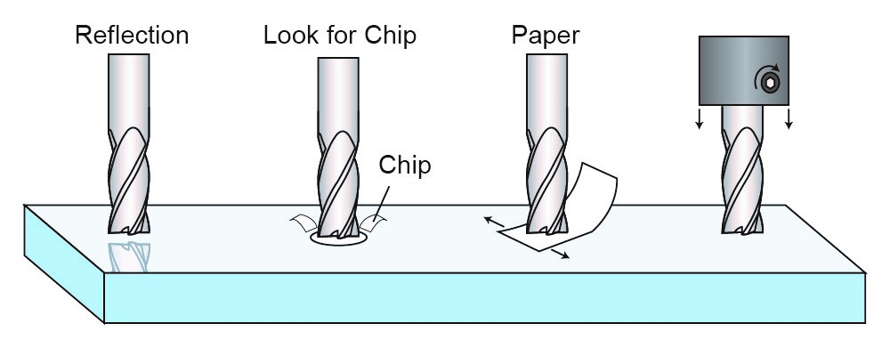
Fig.1。Four techniques for aligning the tool to the workpiece in thez-axis (from left to right): (i) reflection,(ii)芯片,(iii) paper,和(iv)夹头技术。
Tooling Note: This technique requires a reflective surface (e.g.,transparent materials such as PS or PMMA),but otherwise does not require any specific tooling.
步骤1:从稍微高于工件的刀尖开始,with the spindle turned off.
步骤2:从工件的近平面位置看,lower the tool until the tool itself comes in contact with its reflection.
Step 3:将此位置设置为z= 0.
Tip: Placing a piece of paper behind the tool will improve contrast,making it easier to identify when the tool contacts the reflection.A magnifying glass can be used to improve visibility.
Tooling Note: This technique does not require any specific tooling.
步骤1:在主轴运转的情况下,从稍微高于表面的工具开始。(即。,工具应旋转)。
步骤2:Lower the tool towards the surface until either (a) a chip is observed,(b) a mark is made on the surface,or (c) a sound is made from the tool cutting the material.
Step 3:将此位置设置为z= 0.
提示:这种方法最适合大型和平板立铣刀,and can be more difficult with small endmills or any tool that is pointed or round at the tip.注意,这是一种物理接触方法,会使表面有瑕疵。
Tooling Note: This technique requires a small piece of paper of known thickness.
步骤1:从表面上方的刀具开始,关闭主轴。
步骤2:在工具和工件之间放置一张纸(厚度已知)。
Step 3:在来回移动纸张的同时,lower the tool in stepwise increments.
步骤4:Continue lowering the tool until it causes resistance to the sliding piece of paper.
步骤5:将此位置设置为z= the thickness of the paper (e.g.,.003")
提示:练习更多,以便在端铣刀接触到表面时能够轻松识别。.
工具说明:此技术需要一个ER20刀架(31829,来自Tormach工具系统(TTS)和ER20 1/8“夹头(30112,Tormach).
步骤1:Place tool in collet and secure using the setscrew on the side.
步骤2:没有主轴运转,降低工具,直到其刚好位于表面上方。
Step 3:Loosen the setscrew and allow the tool to fall into contact with the workpiece.
步骤4:Tighten the setscrew.
步骤5:将此位置设置为z= 0.
X-Y平面方向
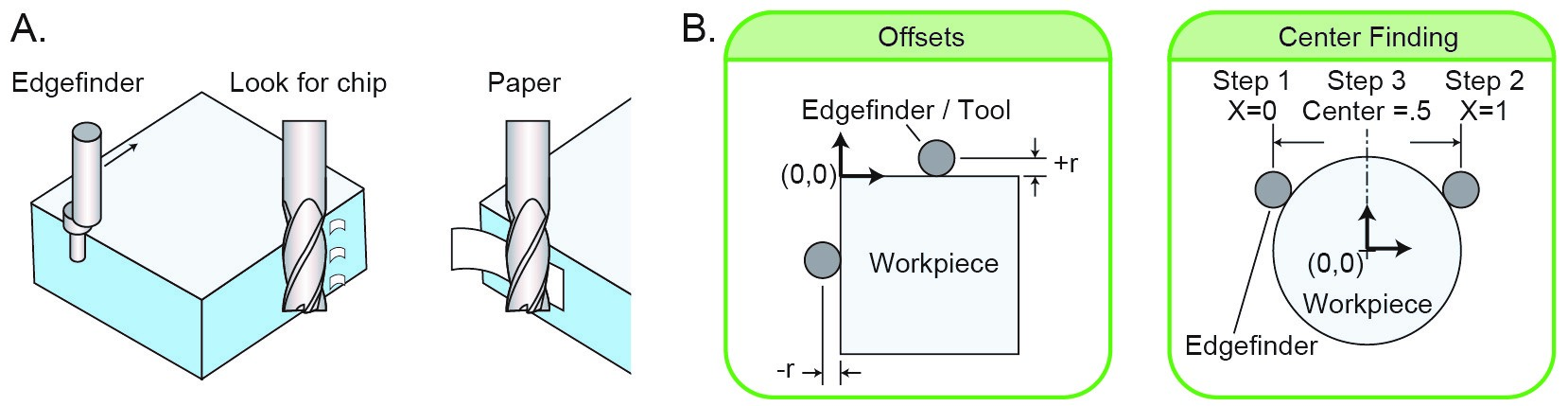
图2。Techniques for aligning the tool in thex–Y飞机。(a)Illustrations of the (i) edgefinder,(ii)芯片,and (iii) paper techniques.(B)工具偏移指南(left)and finding the center of an object(right).
模具备注:
This technique requires an edgefinder (e.g.,#02035186,工业供应理学硕士)。
步骤1:Place edgefinder in collet and start spindle (1000 rpm works well with the edgefinder).
步骤2:使边缘的尖端偏转,使其与初始轴偏心。
Step 3:Starting with thex轴,将边缘朝垂直面移动。封边机的尖端与表面接触后会同心,然后立即回到偏心位置。This sudden "jump" in eccentricity marks the edge.
步骤4:Set the current location to either plus or minus the radius of the tip.参见图。2b有关确定正负偏差的详细信息。
Tooling Note: This technique does not require any specific tooling.
步骤1:从靠近感兴趣面的刀具开始,主轴运行(即。,工具应旋转)。
步骤2:Step the tool towards the surface,until (a) a chip is observed,(b) a mark is made on the surface,or (c) a sound is made from the tool cutting the material.
Step 3:将此位置设置为(加或减)立铣刀半径。
Tip: This method works best for large diameter endmills.注意,这是一种物理接触方法,会使表面有瑕疵。
Tooling Note: This technique requires a small piece of paper of known thickness.
Step 1:Start with the tool near the face of interest with the spindle running
步骤2:用拇指和食指轻轻地抓着,or by pressing it against the surface place a piece of paper between the tool and the surface.
Step 3:向表面移动工具,直到工具拉动纸张。
步骤4:将此位置设置为(加或减)立铣刀半径和纸张厚度之和。
Tip: This method works best for large endmills.
小心:确保手指远离切割工具。
References
1。Guckenberger DJ,de Groot T万安Beebe DJ,Young EWK,"微加工:塑料微流体器件的超快速成型方法“芯片上的实验室,doi:10.1039/c5lc00234f(2015年)。
2。Guckenberger DJ,de Groot T万安Beebe DJ,Young EWK,"Micromilling Techniques I: Securing Thin Plastic Workpieces for Precise Milling“Chips & Tips(2015)。


")
在塑料的微观加工和其他基本制造系统的中间,就专业能力和费用而言,进行了关联。原理检验集中在“最佳方法”的微观加工部分,to empower a client to choose appropriate hardware and devices,and get usable microfluidic parts with insignificant start-up time and exertion.补充资料对数控加工厂的设置作了更广泛的论述。安排,和编程。
Nice post.I love your article here
孩子们的廉价约旦
basketball shoes
jordan 11