Author Archive

How can biosensors provide real-time health monitoring?

Like a ripple spreading outwards on a pond’s surface, aplasmonis a collective oscillation of free electrons in a piece of metal. When the metal interacts with light (in this casek vectorof light satisfies the momentum condition), the collective movement of oscillating electrons at the metal’s surface leads to the propagation of the light along the surface, also known as a surface plasmon. This simple physics rule is very helpful for sensor nanotechnology and optical signal processing applications since the offered advantages are significant, providing a smaller foot-print, lower limits of detection, and multiplexing opportunities. However, using sensors for biomolecule detection requires clever use of light. For example, surface plasmon resonance can be observed in nanohole arrays patterned on very thin gold films. Nanohole arrays can transmit light much more strongly than expected for the nanohole apertures at certain wavelengths. This phenomenon is calledextraordinary optical transmission(EOT) and opens a new avenue for detection of minute amounts of biomolecules.

A nanoplasmonic biosensor was recently developed for real-time monitoring of proteins from live cells in a label-free configuration, thanks to extraordinary optical transmission. The biosensor is structured in a microfluidic device consisting of a cell module and the biosensor module. Microfluidic cell module design is based on a single zigzag channel for directly delivering the secreted proteins to the adjacent biosensor module via a tubing connection. The biosensor module consists of nanoholes fabricated on freestanding SiNx membranes. Antibodies specific tovascular endothelial growth factor(VEGF) are selectively immobilized on the gold nanohole arrays as biorecognition molecules. When the VEGF are captured on the sensor, a change of refractive index proximate to the surface is induced. This change results in a peak shift of the EOT spectrum (Figure 1). By tracing the spectral shifts continuously, the dynamics of cell secretion can be monitored. In this way, the secretion dynamics from live cancer cells are monitored and quantified for 10 hours. The proposed microfluidic device has unique capabilities for multiplexed and label-free detection in a compact footprint, which are promising for miniaturization and integration into lab-on-a-chip devices.

biosensor, microfluidics, extraordinary transmission phenomena, nanohole arrays

microfluidic-integ的设计和工作原理rated biosensor. Cancer cells grow in a zigzag channel, and secreted vascular endothelial growth factor are directly delivered to the adjacent detection module. Nanohole structures fabricated in the detection (biosensor) module are shown in SEM image with a scale bar of 1 μm (bottom left). The images on the right show the characteristic resonance peak (solid line) and EOT spectral shift of the peak upon binding (dashed line). Spectral displacements of the resonance peak based on molecular binding accumulation is shown in the sensorgram to reveal the real-time binding dynamics. Adapted from Liet al.(Lab Chip, 2017).

This technology will have a potentially significant impact on medicine. Most of the patients agree that preventive medicine is preferable to reactive medicine. However, preventive medicine requires frequent physical exams, which can only be maintained by spending substantial time and money at physicians’ offices. The need for frequent check-up exams could be reduced or eliminated by real-time monitoring of the health status by portable biosensors in the future. Developing biosensors that allow real-time monitoring of target biomolecules is a big step towards the addressing this future goal.

To download thefull article for free*click the link below:

Plasmonic nanohole array biosensor for label-free and real-time analysis of live cell secretion

Xiaokang Li, Maria Soler, Cenk I. Özdemir, Alexander Belushkin, Filiz Yesilköy and Hatice Altug

Lab Chip, 2017

DOI:10.1039/C7LC00277G

*Free to access until 7th August 2017.


About the Webwriter

Burcu Gumuscuis a postdoctoral fellow inHerr Labat UC Berkeley in the United States. Her research interests include development of microfluidic devices for quantitative analysis of proteins from single-cells, next generation sequencing, compartmentalized organ-on-chip studies, and desalination of water on the microscale.

Digg This
Reddit This
Stumble Now!
Share on Facebook
Bookmark this on Delicious
Share on LinkedIn
Bookmark this on Technorati
Post on Twitter
Google Buzz (aka. Google Reader)

The future of bioensors

St. Paul’s Cathedral in London has its own unique acoustics. The architecture of the dome allows a whisper to be heard from anywhere within the circular gallery, so-called the whispering gallery. The invention ofwhispering-gallery-mode (WGM) biosensorsis indeed derived by this special gallery in St. Paul’s: just like a sound wave travelling within the dome, a light beam traveling within a glass sphere (in this case, a biosensor) circles multiple paths so that any molecule on the surface can be detected. Thanks to this powerful technique, interactions of unlabeled molecules can be analyzed with high sensitivity in real-time.

In early March of 2017, researchers from Max Planck Institute and University of Exeter published a comprehensive review paper inLab on a Chip, explaining the advances of WGM sensors as scientific laboratory instruments, their development into lab on a chip devices, major challenges on the way towards real-world applications, and potential future applications.

WGM sensors probe the interaction between molecules and electromagnetic waves during a biomolecular reaction, and convert this information to a measurable signal. The probing is made possible thanks to the electromagnetic modes formed inside a resonator with axial symmetry. However, theelectromagnetic wavesslightly extend into the surrounding medium. Any changes in the surrounding medium, and therefore in theevanescent field,造成共振频率的变化the basis of the sensing mechanism. WGMs are capable of sensing this shift in three ways: (1) Resonance frequency shift based sensing: measurable signal is the magnitude of the frequency shift, and the sensitivity of the sensor, which scale with the evanescent field strength at the distortion’s position, i.e. interaction of a single atomic ion with a plasmonic nanoparticle (Figure 1a). (2) Loss based sensing: it is based on the resonator’s energy loss per light wave oscillation, i.e. binding of polystyrene nanoparticles (Figure 1b). (3) Mode-splitting based sensing: a scattering molecule/particle couples clock-wise and counter clock-wise propagating WGMs, resulting in the formation of two different standing wave modes, i.e. deposition of multiple nanoparticles on a surface (Figure 1c).

Whishering gallery mode biosensors

Figure 1. Three different sensing mechanisms of whispering-gallery-mode biosensors. (a) Resonance frequency shift based sensing, (b) loss based sensing, (c) mode-splitting based sensing (from Kim et al., Lab Chip, 2017).

审查也关注一些国际性能teria of WGM sensors, such as single molecule sensitivity, time resolution, stability and specificity. Single molecule sensitivity of WGM sensors depends on the resonator’s size, the surrounding medium and excitation wavelength. Despite the fact that these parameters seem to limit the sensitivity, increasing the electric field inside a nanoscale volume significantly can circumvent this problem. Apart from that, WGM sensors can detect events happening in milliseconds to seconds whereas these detection speeds are mostly limited by the equipment, for example, the laser’s maximum scanning speed. When it comes to stability of WGM sensors, one common problem is reported to be the environmental noise sources, affecting the reliability of the measurements. A variety of methods to reduce those negative effects are further discussed in the review. One another notable functionality is that WGM sensors can be as specific as probing a surface-immobilized receptor molecule reacting with an analyte of interest.

microring resonator based on-chip sensor, pillar-supported high Q cavities

Figure 2. Lab on a chip WGMs. Left and middle images show a microring resonator based on-chip sensor with zoom-in images of different components, and right image shows a pillar-supported high Q cavities (from Kim et al., Lab Chip, 2017).

Lab on a chip applications of WGMs are discussed in two categories in the review (Figure 2): Planar resonators let the light to be coupled into multiple ring-resonators that are connected to channels containing different analytes. This type of resonators is low-cost and allows for in-parallel probing of samples. Pillar-supported high Q cavities is the second type, featuring a high Q factor owing to the air-gap between the substrate and the cavities. Pillar-supported resonators are high-cost due to several fabrication difficulties. Apart from those, droplet-basedin vivosensing via WGM sensors is also addressed as an alternative approach with the possibility of using the analyte medium itself as a resonator. Over the past decade, WGM sensors have been widely exploited to study molecular interactions with high sensitivity and seem to gain more and more attention.

To download thefull article for free*click the link below:

Towards next-generation label-free biosensors: recent advances in whispering gallery mode sensors

Eugene Kim, Martin D. Baaske and Frank Vollmer

Lab Chip, 2017, Critical Review

DOI:10.1039/C6LC01595F

*Free to access until 12th July 2017.

About the Webwriter

Burcu Gumuscuis a postdoctoral fellow inBIOS Lab on a Chip Groupat University of Twente in The Netherlands. Her research interests include development of microfluidic devices for quantitative analysis of proteins of a single-cell, next generation sequencing, compartmentalized organ-on-chip studies, and desalination of water on the microscale.

Digg This
Reddit This
Stumble Now!
Share on Facebook
Bookmark this on Delicious
Share on LinkedIn
Bookmark this on Technorati
Post on Twitter
Google Buzz (aka. Google Reader)

Optical DNA maps

Just like Google maps,DNA mapscan tell us the distance between two genes, and allow us to zoom in on the region of interest. DNA mapping started withhuman genome project, where DNA sequencing techniques opened a way to unveil the genetic information. However, determining the unique places and repetitions of four “chemical letters” found in our DNA—together known as the genes—is a difficult mission due to temperature, pH, and pressure sensitivity of the molecule. DNA mapping technology allows for easy identification of large structural variations in DNA and therefore provides long-range information of the genome and can more.

Optical DNA mapping has emerged in the past decade as a powerful alternative to otherDNA sequencing techniquessince it can easily be applied with reduced risk of DNA damage.Over 100000 basepairs of DNA molecules, which are quite difficult to handle with other techniques, are labeled, stretched, and rendered in a single image. The stretching part is done usingnanochannels(and therefore lab-on-a-chip technology), while the labeling part can be done by either enzymatic or affinity-based techniques (Figure 1). The concept and applications of optical DNA mapping has recently been very well explained in atutorial reviewwritten by Vilhelm Müller andFredrik Westerlundfrom Chalmers University of Technology in Sweden.

Inenzymatic labellingnucleotides at particular regions on a single DNA strand are replaced by new ones using aDNA polymerase. The replacement nucleotides are then utilized to incorporate fluorophores into the DNA strand and allow for visualization. Nicking enzymes and methyl-transferases present two different approaches to employ enzymatic labelling process. While the use of differently colored fluorophores extends the applicability of this technique, the final resolution depends on the degree of stretching and the density of fluorophores on the region.

Affinity-based labellingis based on non-covalent interactions which can be enabled by either denaturation mapping or competitive binding. In denaturation mapping, DNA is heated to discriminate between the bases by their different bond energies. While G-C-basepairs still hold both strands of DNA—due to 3 hydrogen bonds holding them—, A-T-basepairs will melt—due to 2 hydrogen bonds holding them—. At this stage, an intercalating fluorescent dye can be linked to G-C-basepairs, allowing for imaging. Competitive binding relies on the usage of a fluorescent intercalating dye and a molecule selective for either A-T or G-C regions. Therefore, fluorescent dye cannot bind where the selective molecules have already bound. An optical map of DNA molecules can be obtained in this way. Affinity-based labelling is also highly dependent on the degree of stretching.


Optical DNA mapping techniques are useful tools for a wide range of applications from assembly of complex genomes to bacterial plasmid epidemiology. The concept opens up exciting research directions as it allows forautomationof whole analysis using lab-on-a-chip systems and observation of the results usingsmartphones.

optical DNA mapping

Figure 1. Schematic illustration of DNA labelling techniques used in optical DNA mapping. Enzyme-based labelling involves nicking enzymes and methyl-transferases techniques, while affinity-based labelling can be employed by denaturation mapping or competitive binding methods. This figure is adapted from “Optical DNA mapping in nanofluidic devices: principles and applications” paper.

To download thefull article for free*click the link below:

Optical DNA mapping in nanofluidic devices: principles and applications

Vilhelm Müller and Fredrik Westerlund

Lab Chip, 2017, Articles

DOI:10.1039 / C6LC01439A

*Free to access until 5th May 2017.


About the Webwriter

Burcu Gumuscuis a postdoctoral fellow inBIOS Lab on a Chip Groupat University of Twente in The Netherlands. Her research interests include development of microfluidic devices for next generation sequencing, compartmentalized organ-on-chip studies, and desalination of water on the microscale.

Digg This
Reddit This
Stumble Now!
Share on Facebook
Bookmark this on Delicious
Share on LinkedIn
Bookmark this on Technorati
Post on Twitter
Google Buzz (aka. Google Reader)

Sample-in-answer-out

You have worked hard all year and wanted to treat yourself with something different for the summer. You decided to arrange a journey to South-Africa to enjoy the beautiful natural scenery. Discovering the range of wildlife in immense national parks, hiking in mountains, and meeting with warm locals made your journey unforgettable. You arrived at one of the best photography spots in a national park just before the sunset. While focussing on capturing the best image from the picturesque scenery, you got bitten by aMarsh mosquito, perhaps infected with aPlasmodium falciparumparasite. This parasite is known for causingmalaria, the most significant parasitic disease of humans. You are not the only one: approximately 30,000 travellers from industrialized countries contract malaria each year. During the next 14 days, this parasite will differentiate and proliferate in the body. It will invade and destroy the red blood cells, eventually affecting the liver, spleen, and brain functionality. A few days after the bite, you found a small-scale laboratory for the malaria diagnosis test, but there was a problem: this laboratory can detect malaria only if you have 50-100 parasites per microliter of blood, occurring when the patient carries the parasite for weeks. You, then, had to find a larger laboratory equipped with a benchtop loop-mediated isothermal DNA amplification (LAMP) system, which can detect 1 malaria parasite per microlitre of blood. You wished there was a highly sensitive device for malaria diagnosis at the point of need. Well, we might have some good news for you.

Modern nucleic acid testing methods of malaria detection, such as LAMP, enable high sensitivity, high specificity, robust, and rapid analyses for asymptomatic infections. As performing these methods requires bulky and costly peripheral equipment and trained technicians, access to such equipment in rural areas is unlikely. Fortunately, researchers in Pennsylvania State University recently introduced astand-alone, portable, and high sensitivity systemthat can perform“sample-in-answer-out”分析。该系统由一个光盘d a reader unit (Figure 1). The compact disc includes valves and microfluidic channels, where the blood sample is processed using magnetic beads. The reader unit can automatically perform all analysis steps including DNA purification, elution, amplification, and real-time detection. For a real demonstration of how the test is performed, the movie included below is well worth the watch. Test results can be displayed on a LCD screen or a smartphone within40 minutes. The system can detect down to0.6 parasites per microliter of blood. Each test costs around $1. With these specifications, this technology has the opportunity to create a new paradigm in molecular diagnosis at the point of care.

malaria detection test

Figure 1. Schematic view of an assembled compact disc made of PMMA; AnyMDX reading unit consisting of a magnet, heater plate, optical detection system, and LCD screen; and the illustration of integrated sample processing steps on the compact disc. The technique is based on DNA-carrying magnetic beads actuated against stationary reagent droplets.

To download thefull article for free*click the link below:

A field-deployable mobile molecular diagnostic system for malaria at the point of need

Gihoon Choi, Daniel Song, Sony Shrestha, Jun Miao, Liwang Cuic and Weihua Guan

Lab Chip2016年的文章

DOI:10.1039/C6LC01078D

About the Webwriter

Burcu Gumuscuis a postdoctoral fellow inBIOS Lab on a Chip Groupat University of Twente in The Netherlands. Her research interests includedevelopment of microfluidic devices for next generation sequencing, compartmentalized organ-on-chip studies, and desalination of water on the microscale.

Digg This
Reddit This
Stumble Now!
Share on Facebook
Bookmark this on Delicious
Share on LinkedIn
Bookmark this on Technorati
Post on Twitter
Google Buzz (aka. Google Reader)

What can a magnet do?

The magic of magnetism can be shown through a simple classroom demonstration of bringing two magnetic pieces together and then trying to pull them apart. The attraction between the opposite poles of the magnets becomes very apparent as you struggle to tear them apart. This simple concept can be applied to lab-on-a-chip devices toeliminate the need for off-device hardware with power requirements, and therefore, enable the use of lab-on-a-chip technology in low-resource settings.

The majority of existing lab-on-a-chip systems use manual pipettes, syringe pumps, or pressure pump systems to manipulate the fluid flow. The dependence on off-chip hardware, however, makes the integration of these systems into low-cost environments rather challenging. Researchers in both, academia and industry think that this challenge can be addressed by “手动self-contained microfluidic devices”, which has gained significant attention over the past couple of years. In line with this objective, magnetically-adhesive based valves have for the first time shown to control fluid flow in a microfluidic device in a recent collaboration work bySandia National LabsandQorvo Inc.Here, the “magnetic-adhesive based valve” simply consists of a disk magnet seated on a thin ring of adhesive material.

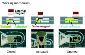
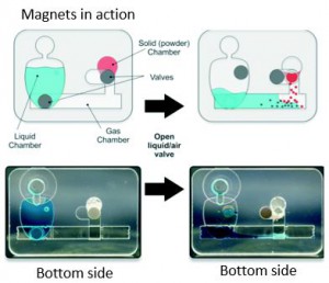
In this study, a microfluidic device is designed to perform bioassays and contains a port connecting two chambers in different planes. The port is closed by an internal magnet located on a pressure-sensitive adhesive tape, and is opened by the help of an external magnet which displaces the internal magnet (figure 1). When the port is open, the reagents can flow in the microchannels, as shown in figure 2. The adhesive tape prevents any leakage within the microchip, while the magnet serves as an actuatable gate for reagents. The microfluidic device, therefore, allows for storage and on-demand transport of different types of reagents (both liquid, solid, and gas) to perform bioassays.

Magnetic-adhesive based valves are fabricated at the millimeter-scale, however, it is possible to manufacture micron-sized valves depending on the resolution of the laser ablation system used to cut the valve layout. Design considerations and characterization of magnetic-adhesive based valves are further addressed inthe paper. Apart from this, the self-contained device is made of low-cost materials (such asPMMAand magnetic alloys), resulting in a fabrication cost as low as 0.2 dollars per chip. As portable and low-cost devices start to draw increasing attention in lab-on-a-chip technology, this work might be an important milestone for next generation micro total analysis systems.

Magnetic valves for lab on a chip sytems

Figure 1. Schematic and photos of magnetic-adhesive based valve working mechanism.

Magnetic valves for lab on a chip devices

Figure 2. Controlled transport and reaction of the stored components in a simple, power- and instrument-free manner in a three chambered microfluidic device.

This is a recently publishedHot articleand you can download it forfree* by clicking the link below:

Magnetic-adhesive based valves for microfluidic devices used in low-resource settings

Jason C. Harper, Jenna M. Andrews, Candice Ben, Andrew C. Hunt, Jaclyn K. Murton, Bryan D. Carson, George D. Bachand, Julie A. Lovchik, William D. Arndt, Melissa R. Finley and Thayne L. Edwards

Lab Chip, 2016, Recent HOT Articles

DOI: 10.1039 / C6LC00858E


About the Webwriter

Burcu Gumuscuis a postdoctoral fellow inBIOS Lab on a Chip Groupat University of Twente in The Netherlands.

Her research interests include development of microfluidic devices for next generation sequencing, compartmentalized organ-on-chip studies, and desalination of water on the microscale .

Digg This
Reddit This
Stumble Now!
Share on Facebook
Bookmark this on Delicious
Share on LinkedIn
Bookmark this on Technorati
Post on Twitter
Google Buzz (aka. Google Reader)